+86-18168358320
Welcome to Wuxi Jinlianshun Aluminum Co., Ltd Website! Aluminum Heat Exchangers Manufacturers

 2026.07.11
 Content
On a 38°C summer day, a single-drum vibratory roller packing asphalt can push coolant temperatures past 105°C within 20 minutes of operation. Unlike highway trucks, road rollers combine continuous high load, low ground speed, and minimal natural airflow — a perfect storm for thermal stress. The engine alone dumps roughly 40% of its fuel energy into the cooling system, while the hydrostatic transmission and vibratory eccentric masses contribute another 15–20% of total heat load.
Road rollers operate in some of the harshest conditions imaginable. Fine dust clogs fins, vibration rattles connections loose, and ambient temperatures at paving sites routinely exceed 45°C. A dedicated road roller heat exchanger is engineered specifically for these constraints. It prioritizes vibration resistance, compact packaging, and tolerance to airborne debris — characteristics that generic off-the-shelf radiators simply cannot match.
The primary heat sources demanding active cooling in a modern roller are:
If any one of these circuits exceeds its design temperature range, the results cascade quickly. Hydraulic oil viscosity drops, pump efficiency degrades, and in severe cases the ECU will limit engine power to protect internal components. The right heat exchanger not only prevents these failures but also maintains optimal fluid temperatures that lengthen the service life of expensive drive components.
Two heat exchanger architectures dominate the construction machinery segment, but their real-world behavior in road roller applications differs sharply. The table below quantifies the performance gap between a typical brazed aluminum plate-fin core and a copper-brass shell-and-tube unit of equivalent nominal cooling capacity.
| Parameter | Aluminum Plate-Fin | Shell-and-Tube |
|---|---|---|
| Core weight | 22 kg | 41 kg |
| Heat transfer density | 1850 W/m²·K | 780 W/m²·K |
| Envelope volume | 0.18 m³ | 0.34 m³ |
| Vibration endurance (G-rating) | 8 G (tested per JB/T 5993) | 5 G |
| Typical relative cost | 1.0 (baseline) | 1.3–1.5 |
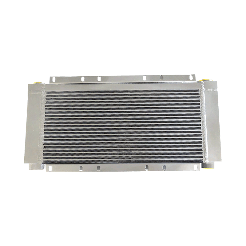
Aluminum plate-fin designs deliver nearly 2.4 times the heat transfer density of a shell-and-tube unit, largely due to the secondary surface area created by the offset fins. This allows a much smaller frontal area — critical in road rollers where engine bay space is consumed by articulation joints, pumps, and counterweights. The weight savings also matter directly: 19 kg less hanging off the rear frame reduces structural stress on mounting brackets and isolation mounts.
Corrosion resistance in dusty, humid environments is another factor. While copper-brass materials perform well in clean marine cooling circuits, they are susceptible to ammonia-based corrosion from agricultural fertilizers or certain asphalt additives that can be present on job sites. Aluminum cores with proper coatings and sacrificial zinc anodes show superior life in road roller applications, particularly when paired with periodic fin cleaning. The brazed construction also eliminates the tube-to-tubesheet joints that become leak paths in shell-and-tube units after thousands of vibration cycles.
Matching a heat exchanger to a road roller is not about simply picking the same core size that came out of the old machine. Operating conditions change, engine tunes get adjusted, and original equipment margins may have been too slim for tropical climates. These five parameters, when verified against the actual machine data, eliminate guesswork.
Our engineering team regularly uses these five parameters to configure custom road roller heat exchanger packages that drop into existing mounting frames with zero fabrication work. Moving from a generic replacement core to a spec-matched unit often drops peak coolant temperatures by 4–6°C under identical load conditions.
Let’s work through a real example. A 10-ton single-drum soil compactor is fitted with a 130 kW diesel engine. The manufacturer’s data sheet states coolant heat rejection of 65 kW at 2,200 rpm. The job site is in southern Spain, where summer ambient reaches 44°C, and the machine is equipped with a variable-speed hydraulic fan. The target is a top tank temperature no higher than 98°C.
Step 1: Determine the required thermal capacity. Start with the engine heat rejection of 65 kW. Add 5 kW for the hydrostatic transmission oil cooler loop that will be integrated into the same core (typical side-by-side or stacked configuration). Total design load: 70 kW.
Step 2: Calculate the logarithmic mean temperature difference (LMTD). Assume coolant inlet 98°C, coolant outlet 92°C; ambient air inlet 44°C, air outlet 78°C (estimated). LMTD = [(98-78) - (92-44)] / ln[(98-78)/(92-44)] = (20 - 48) / ln(20/48) = -28 / ln(0.4167) = -28 / (-0.8755) = 32.0°C.
Step 3: Select a core with known UA value. A typical plate-fin core for this duty class offers a UA of roughly 2.4 kW/°C at design air and coolant flows. Multiply UA by LMTD: 2.4 × 32.0 = 76.8 kW — this exceeds the required 70 kW, so the core is adequate with a small margin.
Step 4: Verify coolant-side pressure drop. At the required flow rate of 240 L/min, the core adds approximately 18 kPa to the circuit. The engine water pump maintains a system pressure of 120 kPa, so this delta-P is acceptable. If pressure drop had exceeded 30 kPa, a core with wider internal channels would be necessary, even if it meant increasing the frontal area slightly.
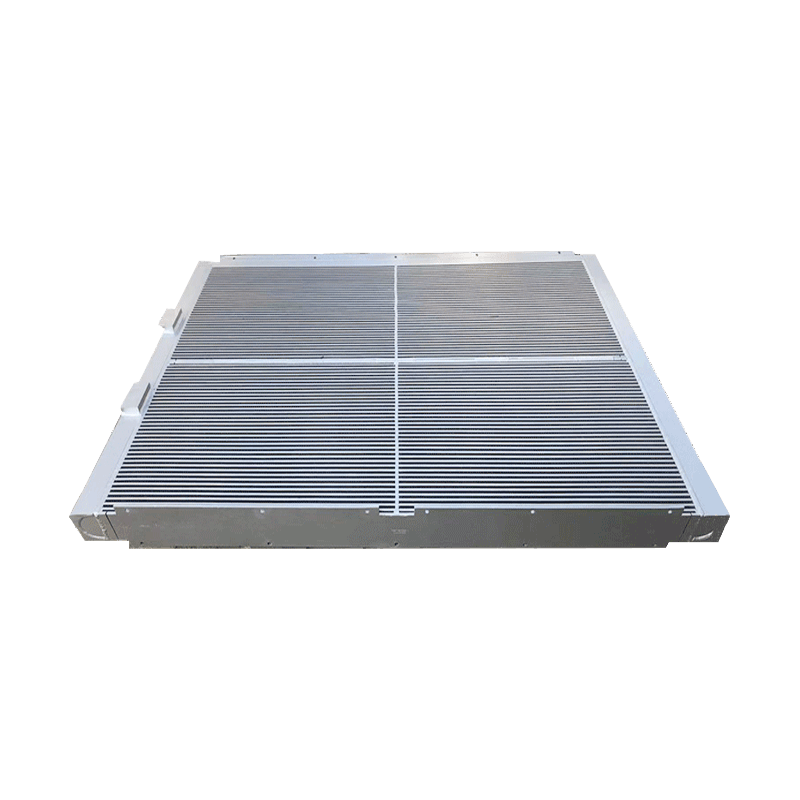
These calculations take about 15 minutes when the specification data is at hand. For more complex multi-circuit cooling packs, high-thermal-conductivity plate-fin radiators can be configured with separate oil and coolant sections in a single brazed assembly, avoiding the weight and complexity of bolted-together modules.
Most heat exchanger failures on road rollers announce themselves gradually: a rising temperature gauge, a small puddle under the machine, or reduced cooling fan cycling frequency. Catching these early prevents the domino effect of overheating that can warp cylinder heads or score hydrostatic pump pistons. The table below maps the three most frequent failure modes.
| Symptom | Root Cause | Diagnostic Check | Repair Approach |
|---|---|---|---|
| Engine temperature creeps up under load; fan runs continuously | Air-side fin blockage from dust and asphalt particles | Hold a bright light behind the core; if less than 70% of the area transmits light, fins are clogged | Remove core, back-flush with low-pressure water from the fan side. Use a fin comb to straighten bent fins. In severe cases, ultrasonic cleaning |
| Coolant loss without visible external leak; white exhaust smoke | Header crack or tube-to-header joint leak (braze failure) | Pressure-test the core to 200 kPa with air and submerge in water; look for bubble stream | For small pinholes, a specialized aluminum epoxy repair may last 500–1,000 hours. Cracked headers require core replacement |
| Hydraulic oil temperature warning; oil cooler inlet and outlet temperatures nearly equal | Internal passage blockage from degraded O-ring material or sludge | Measure oil-side pressure drop across core at rated flow; if delta-P exceeds 50% of original spec, passages are restricted | Flush oil circuit with a low-viscosity cleaning fluid. If unresponsive, replace the oil cooler section; internal blockages cannot be mechanically rodded in plate-fin designs |
A less frequent but equally disruptive failure is vibration-induced fretting at the mounting brackets. Over thousands of hours, the constant low-amplitude oscillation wears through the aluminum side supports, eventually creating a crack that propagates into the header. Inspect bracket weld areas every 500 operating hours with a dye penetrant kit if the roller is used predominantly on vibratory compaction work.
There is a direct correlation between fin cleanliness and heat exchanger survival. Data from fleet maintenance records across 120 road rollers showed that cores cleaned every 250 operating hours had a mean time between failures 2.3 times longer than those cleaned only at the annual service. The checklist below consolidates 15 years of field experience into a simple routine.
For rollers working on coastal projects, where salt-laden air accelerates galvanic corrosion, add a monthly freshwater rinse of the core exterior — even when the machine is operational. The extra five minutes of downtime saves thousands in premature core replacement.
No heat exchanger lasts forever, particularly under the relentless vibration and thermal cycling of a road roller. Waiting until a catastrophic overheat event occurs is a false economy — the cost of a new core is trivial compared to a rebuilt engine or hydrostatic pump. Three quantitative thresholds signal that replacement is the smarter path.
When any one of these conditions is met, sourcing a replacement that matches the machine’s actual thermal duty — not just the part number — restores design-intent cooling performance. The wide interchangeability of plate-fin cores across roller makes and models means that an upgraded aluminum unit can often be configured at a cost comparable to an OEM shell-and-tube replacement, while delivering better heat rejection margins and lower installed weight.
Technological innovation, quality refinement, integrity-based, the pursuit of excellence. Market-oriented, “customer satisfaction” as the core, all services to customers. Aluminum Heat Exchangers Manufacturers in China, Aluminum Radiator Heat Exchangers Solutions
ADD: No.59-1 Changkang Road, Wuxi Binhu District, Wuxi City, Jiangsu Province, China.
MP(Whatsapp):+86-18168358320
MP(Whatsapp):+86-18068169815
MP(Whatsapp):+86-18914157685
Copyright © Wuxi Jinlianshun Aluminum Co. Ltd. All Rights Reserved.

 English
 русский