 +86-18168358320
Welcome to Wuxi Jinlianshun Aluminum Co., Ltd Website! Aluminum Heat Exchangers Manufacturers

 2026.08.28
 Content
A hydraulic system driven by a 75 hp diesel engine can convert roughly 25 hp of its input into pure heat. That energy does not vanish; it collects in the oil, raising its temperature shift after shift. When the reservoir walls and return lines alone cannot shed the load, oil temperature climbs until viscosity, seals, and pump life start paying the bill.
This is why a hydraulic system heat exchanger is standard equipment on most modern machines rather than an optional accessory. The sections below explain how these coolers work, where air-cooled and water-cooled designs each fit, how to size one against a real duty cycle, and which maintenance habits keep a cooler performing for the life of the machine.
Most of the heat in a hydraulic circuit comes from pressure drop. Whenever oil falls from high pressure to low pressure without doing mechanical work, that difference turns into heat. The usual offenders are:
A common field rule holds that about one-third of installed input horsepower ends up as heat in a typical system. It is an average, not a law, and duty cycle can move the real number sharply in either direction, but it gives engineers a defensible starting point before test data exists.
The cost of ignoring that heat is predictable. As oil warms, viscosity drops, lubricating films thin out, and internal leakage grows, which generates still more heat in a self-reinforcing loop. Oxidation accelerates, additives deplete faster, and seal compounds harden. Holding the oil roughly within 40 to 60°C (104 to 140°F) remains the cheapest insurance a hydraulic system can carry.
The principle is straightforward: hot oil flows along one side of a thin wall, a cooler medium flows along the other, and heat crosses by conduction before being carried off by convection. The engineering challenge is achieving this in a small, light package, and that is where surface area decides the outcome.
Fins provide that area. Corrugated metal fins sandwiched between flat plates multiply the heat-transfer surface far beyond what a bare tube can offer. In a brazed aluminum plate-fin core, alternating passages carry oil and the cooling medium, and the fins between them are tuned in height and density to balance heat rejection against pressure drop. Because aluminum conducts heat well and weighs little, a plate-fin core can reject a serious heat load from a block small enough to bolt beside the pump on a mobile machine.
The short answer: choose air cooling for mobile equipment and water cooling where a dependable water circuit already exists. Everything else is detail.
Air-cooled units pass hot oil through a finned core while a fan drives ambient air across it. No water supply or plumbing is needed, which makes them the default on excavators, loaders, cranes, agricultural tractors, and nearly all off-highway equipment. Their weakness is the weather: a cooler sized for 25°C air will struggle on a 45°C jobsite, and fins choked with dust or crop residue lose capacity quickly.
Water-cooled units exchange heat between oil and water, typically in a shell-and-tube or plate-type body. They are compact, stable, and indifferent to ambient air, which suits industrial power units that already have a cooling tower or chilled water line. The trade-offs are water-side fouling, the need for water treatment, and a small but real risk of cross-contamination should a boundary fail.
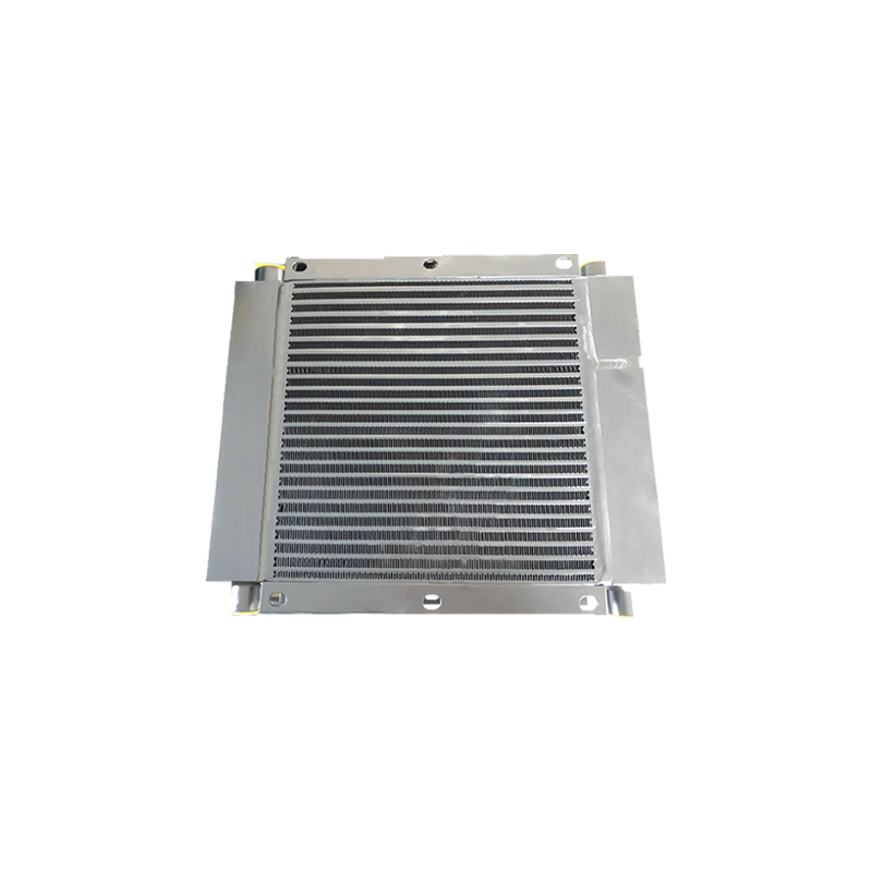 Plate-Fin Water-Cooled Cooler for Industrial Fluid CoolingWater-cooled units suit plants with a cooling tower or chilled water line, and this plate-fin design maximizes heat transfer surface in a compact, corrosion-resistant body for stable temperature control under high pressure and temperature conditions.View Product →
| Selection factor | Air-cooled cooler | Water-cooled cooler |
|---|---|---|
| Extra infrastructure | Fan and drive power only | Water supply, drainage, treatment |
| Typical setting | Mobile and off-highway machines | Industrial power units and plants |
| Hot ambient behavior | Capacity falls as air warms | Stable while water supply holds |
| Footprint and weight | Larger core plus fan assembly | Compact for equivalent duty |
| Primary upkeep task | Keeping fins clean | Preventing water-side scale |
Begin with the heat load, not the catalog. Applying the one-third rule to a 75 hp system gives about 25 hp of heat, and since 1 hp equals roughly 2,545 BTU/hr, the target lands near 64,000 BTU/hr, or close to 19 kW. Correct that figure with the variables that actually move it:
Air-cooled coolers are rated by approach temperature, meaning how close the oil outlet can get to incoming air. A cooler holding a 10°C approach works far harder than one specified at 20°C, so the rating condition must match your climate. Oil-side pressure drop is the other constraint, because too much restriction starves the return line; a few tenths of a bar at rated flow is a typical target.
Engineers who want the numbers behind these decisions can work through our guide to the key thermal performance metrics for hydraulic system heat exchangers before comparing supplier datasheets.
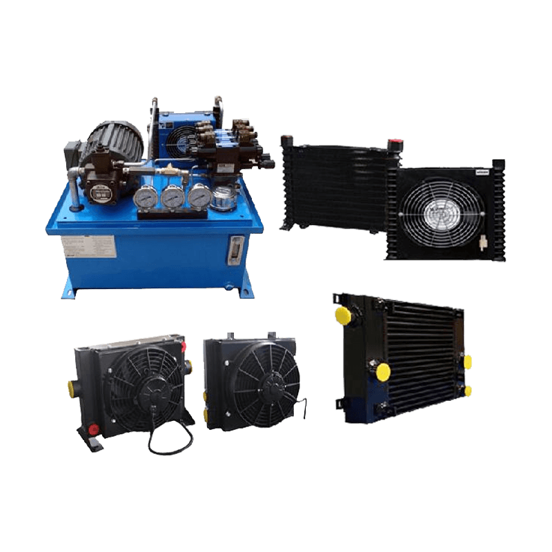 Aluminum Heat Exchangers for Hydraulic SystemsMobile machinery combines high heat loads with tight envelopes, vibration, and weight limits. Aluminum plate-fin heat exchangers address these constraints, making them a practical reference point when comparing hydraulic cooling suppliers.View Product →
Mobile machines pile up the hardest constraints at once: high heat loads, tight installation envelopes, constant vibration, and a direct penalty for every kilogram of weight. Brazed aluminum plate-fin construction answers all four, which explains why it dominates excavator, loader, crane, and drilling rig cooling packages today.
A plate-fin core is built from stacked layers, so a manufacturer can adapt the exchanger to the machine instead of forcing the machine to accept a catalog part. Fin density can rise for cool, dusty climates or fall for hot, dirty air; port sizes and orientations can match existing plumbing; and the overall block can be shaped around whatever space remains near the engine radiator. The practical test for a buyer is whether the supplier can start from your flow rate, heat load, and mounting dimensions and return a core that drops in with minimal rework.
Customizable Aluminum Hydraulic System Heat ExchangerBecause plate-fin cores are built from stacked layers, fin density, port orientation, and block shape can match each machine's heat load and mounting space, allowing a drop-in core with minimal rework instead of a one-size-fits-all unit.View Product →
That is exactly how the aluminum hydraulic system heat exchanger platform is configured: cores are built around each application's thermal load and space limits rather than sold as one-size-fits-all units.
A correctly sized cooler still underperforms when it is installed or maintained badly. These practices cover most field problems:
Temperature trend tracking deserves special emphasis because it costs nothing. When a machine that once settled at 55°C starts settling at 70°C on the same jobsite, something changed, and a structured method for diagnosing failures and performance issues in hydraulic system heat exchangers will separate a dirty core from a tired fan or an internal leak in minutes rather than days.
A hydraulic heat exchanger earns its place by holding oil in the viscosity band where pumps, valves, and seals were designed to operate. Size it against the real heat load including worst-case ambient, pick air or water cooling based on the machine's infrastructure, favor construction that survives vibration and dirt, and then keep the fins and the fluid clean. Machines specified this way spend their shifts working instead of cooling down, and the cooler becomes the quietest component on board.
Technological innovation, quality refinement, integrity-based, the pursuit of excellence. Market-oriented, “customer satisfaction” as the core, all services to customers. Aluminum Heat Exchangers Manufacturers in China, Aluminum Radiator Heat Exchangers Solutions
ADD: No.59-1 Changkang Road, Wuxi Binhu District, Wuxi City, Jiangsu Province, China.
MP(Whatsapp):+86-18168358320
MP(Whatsapp):+86-18068169815
MP(Whatsapp):+86-18914157685
Copyright © Wuxi Jinlianshun Aluminum Co. Ltd. All Rights Reserved.

 English
 русский